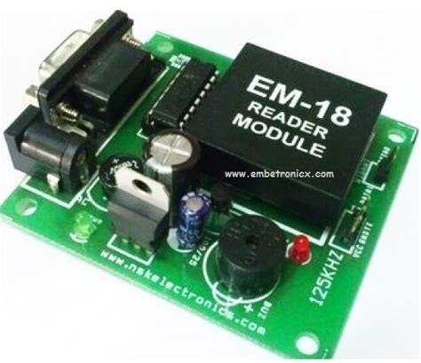
rfid door access system using pic16f877a Here we are using PIC Microcontroller PIC16F877A for interfacing RFID. We will simply read the unique identification no. of RFID tags using UART serial communication and . $8.00
0 · pic16f877a rfid
1 · pic16f877a interfacing circuit diagram
$16.99

pic16f877a rfid
To address this, we have developed a Smart Door Lock System that utilizes both RFID technology and keypad functionality, powered by the advanced PIC16F877A . Here we are using PIC Microcontroller PIC16F877A for interfacing RFID. We will simply read the unique identification no. of RFID tags using UART serial communication and . Here we are using PIC Microcontroller PIC16F877A for interfacing RFID. We will simply read the unique identification no. of RFID tags using UART serial communication and . To make most use of this, this paper proposes a smart unlocking mechanism for doors of high security importance. This is made possible by employing IoT Technology, which .
I have been working on my school project for couple of weeks and I'm trying to make RFID Door Lock by using Pic16f877A and RDM6300 RFID reader , I made a code works . Here we are using PIC Microcontroller PIC16F877A for interfacing RFID. We will simply read the unique identification no. of RFID tags and display it on 16×2 LCD. RFID .This system is designed around PIC microcontroller PIC16F877A and RFID Reader RDM6300, which is 125 kHz reader. It also features LCD 1602 display, a buzzer, servo SG90 and a .
It can be directly interfaced with microcontrollers using UART and with PC using an RS232 converter. Just power the module, and it will read any RFID card within range. It will .PIC16F877A, XC8 compiler,MP Lab, Keypad, Solenoid Door Lock - thuyavansc/Pic-Password-Based-Door-Lock-System I have been working on my school project for couple of weeks and I'm trying to make RFID Door Lock by using Pic16f877A and RDM6300 RFID reader , I made a code works . I'm working on a Door Lock system project with RFID module using Pic16f877a and I want to add QR reader to my project and make different QR codes and sore their information .
This project showcases two methods to use a functional keypad accessed security system for hotel rooms, implemented using a PIC microcontroller and programmed in C,C++. The system . Here we are using PIC Microcontroller PIC16F877A for interfacing RFID. We will simply read the unique identification no. of RFID tags using UART serial communication and . To make most use of this, this paper proposes a smart unlocking mechanism for doors of high security importance. This is made possible by employing IoT Technology, which .
I have been working on my school project for couple of weeks and I'm trying to make RFID Door Lock by using Pic16f877A and RDM6300 RFID reader , I made a code works . Here we are using PIC Microcontroller PIC16F877A for interfacing RFID. We will simply read the unique identification no. of RFID tags and display it on 16×2 LCD. RFID .
This system is designed around PIC microcontroller PIC16F877A and RFID Reader RDM6300, which is 125 kHz reader. It also features LCD 1602 display, a buzzer, servo SG90 and a .
It can be directly interfaced with microcontrollers using UART and with PC using an RS232 converter. Just power the module, and it will read any RFID card within range. It will .

PIC16F877A, XC8 compiler,MP Lab, Keypad, Solenoid Door Lock - thuyavansc/Pic-Password-Based-Door-Lock-System
I have been working on my school project for couple of weeks and I'm trying to make RFID Door Lock by using Pic16f877A and RDM6300 RFID reader , I made a code works . I'm working on a Door Lock system project with RFID module using Pic16f877a and I want to add QR reader to my project and make different QR codes and sore their information .
pic16f877a interfacing circuit diagram
smart sim card activation
The app includes a Host-Based Card Emulated (HCE) NFC tag and the associated NFC reader. You learn how to setup your own HCE application and how you can communicate with the .
rfid door access system using pic16f877a|pic16f877a interfacing circuit diagram