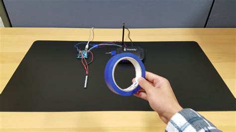
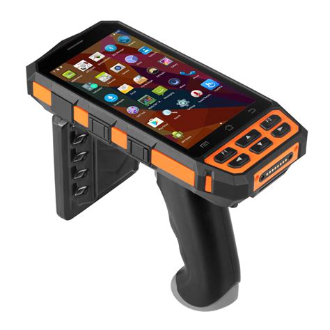
long range rfid reader circuit diagram a) LC circuit must be tuned to the carrier frequency of the reader. b) Maximize Q . MobileKnowledge is a team of HW, SW and system engineers, experts in smart, .
0 · uhf rfid reader arduino
1 · long range rfid tracking
2 · long range rfid scanner
3 · long range rfid reader price
4 · long range rfid reader arduino
5 · long range passive rfid reader
6 · long range nfc
7 · best long range rfid reader
NFCPassportReader. This package handles reading an NFC Enabled passport using iOS 13 .
13.56 MHz reader designer. The schematic included in this chapter is for the 13.56 MHz .

aruba pec rinnovo smart card
a) LC circuit must be tuned to the carrier frequency of the reader. b) Maximize Q .This section is written for RF coil designers and RFID system engineers. It reviews .a) LC circuit must be tuned to the carrier frequency of the reader. b) Maximize Q of the tuned .

uhf rfid reader arduino
This section is written for RF coil designers and RFID system engineers. It reviews basic .RFID uses radio waves produced by a reader to detect the presence of (then read the data .
13.56 MHz reader designer. The schematic included in this chapter is for the 13.56 MHz Reference Reader included in the DV103003 microID™ Developer’s Kit. The circuit is designed for short read-range applica-tions. The basic design can be modified for long-range or other applications with MCRF355/360 devices. Ana) LC circuit must be tuned to the carrier frequency of the reader. b) Maximize Q of the tuned circuit. c) Maximize antenna size within physical limit of application requirement. See Application Note “ Antenna Circuit Design for RFID Applications” (DS00710) for more details. Read-Only Device, Read/Write Device:This section is written for RF coil designers and RFID system engineers. It reviews basic electromagnetic theories on antenna coils, a procedure for coil design, calculation and measurement of inductance, an antenna tuning method, and read range in RFID applications. REVIEW OF A BASIC THEORY FOR RFID ANTENNA DESIGN Current and Magnetic Fields In this tutorial, we discussed how the RFID Reader Module works and how we can use it with Arduino. For Interfacing RFID Reader Module RC522 with Arduino, we have provided Circuit Connection, Arduino Code, and a step-by-step guide.
long range rfid tracking
long range rfid scanner
RFID uses radio waves produced by a reader to detect the presence of (then read the data stored on) an RFID tag. Tags are embedded in small items like cards, buttons, or tiny capsules. These readers also use radio waves in some systems to write new information to the tags.

AWID's LR-3000 reader is a rugged, weather resistant, long-range Radio Frequency Identification (RFID) reader that works with a selection of hands-free and vehicle mounted credentials. This reader comes with a unique combination of long read range, small size, .
I'm trying to make a long-range RFID reader which could read 13.56MHz passive RFID tags at a minimum distance of 1m. I'm planning to use an Arduino Uno for this purpose. But I'm not sure of what reader module should I use.
They've demonstrated how to make a device that can read the cards using a commercial RFID reader commonly found in fixed, in-building installations (which is instead mounted in a briefcase) and then connected to an Arduino to receive the card data and write it . An RFID reader circuit diagram is a visual representation of the components used to create an RFID reader. This includes power supplies, microcontrollers, transistors, and input/output devices. The diagram shows the connections between these components and how they interact with each other. The range of a passive RFID system is 1 to 30 meters long. However, it depends on the transmitted frequency. So, if you want to track an item’s location, you’d need a lot of RFID readers.13.56 MHz reader designer. The schematic included in this chapter is for the 13.56 MHz Reference Reader included in the DV103003 microID™ Developer’s Kit. The circuit is designed for short read-range applica-tions. The basic design can be modified for long-range or other applications with MCRF355/360 devices. An
a) LC circuit must be tuned to the carrier frequency of the reader. b) Maximize Q of the tuned circuit. c) Maximize antenna size within physical limit of application requirement. See Application Note “ Antenna Circuit Design for RFID Applications” (DS00710) for more details. Read-Only Device, Read/Write Device:This section is written for RF coil designers and RFID system engineers. It reviews basic electromagnetic theories on antenna coils, a procedure for coil design, calculation and measurement of inductance, an antenna tuning method, and read range in RFID applications. REVIEW OF A BASIC THEORY FOR RFID ANTENNA DESIGN Current and Magnetic Fields
In this tutorial, we discussed how the RFID Reader Module works and how we can use it with Arduino. For Interfacing RFID Reader Module RC522 with Arduino, we have provided Circuit Connection, Arduino Code, and a step-by-step guide.RFID uses radio waves produced by a reader to detect the presence of (then read the data stored on) an RFID tag. Tags are embedded in small items like cards, buttons, or tiny capsules. These readers also use radio waves in some systems to write new information to the tags.
AWID's LR-3000 reader is a rugged, weather resistant, long-range Radio Frequency Identification (RFID) reader that works with a selection of hands-free and vehicle mounted credentials. This reader comes with a unique combination of long read range, small size, . I'm trying to make a long-range RFID reader which could read 13.56MHz passive RFID tags at a minimum distance of 1m. I'm planning to use an Arduino Uno for this purpose. But I'm not sure of what reader module should I use.They've demonstrated how to make a device that can read the cards using a commercial RFID reader commonly found in fixed, in-building installations (which is instead mounted in a briefcase) and then connected to an Arduino to receive the card data and write it .
An RFID reader circuit diagram is a visual representation of the components used to create an RFID reader. This includes power supplies, microcontrollers, transistors, and input/output devices. The diagram shows the connections between these components and how they interact with each other.
long range rfid reader price
long range rfid reader arduino
Statewide coverage is the hallmark of the Auburn Sports Network's exclusive coverage of Auburn football. All home and away games are broadcast across the entire state of Alabama plus portions of .
long range rfid reader circuit diagram|best long range rfid reader